Product Description
Product Description
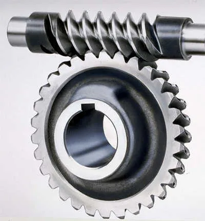
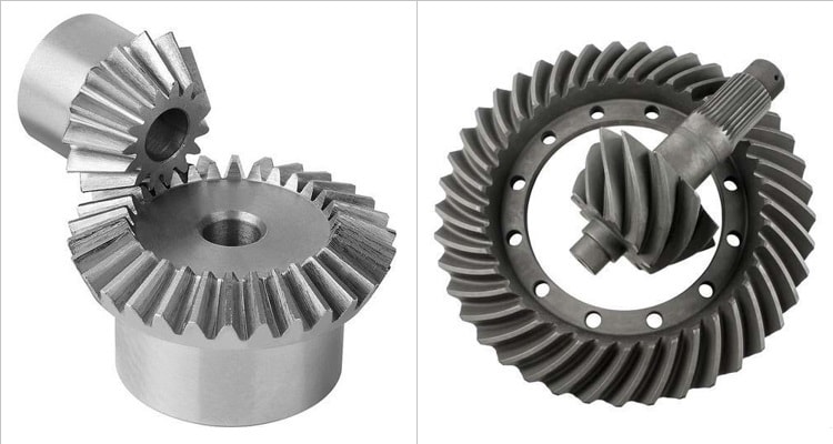
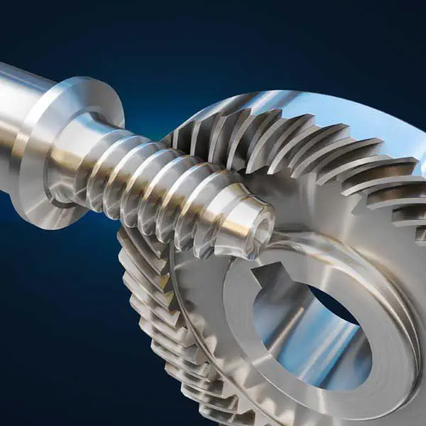
Spur Gear/ Helical Gear/ Straight Bevel Gear/ Spiral Bevel Gear/ Worm Gear
With more than 10yeas experience in the field of gear manufacturing, CHINAMFG can supply various kinds of gears, such like Spur Gear/ Helical Gear/ Straight Bevel Gear/ Spiral Bevel Gear/ Worm Gear. It’s equipped with CNC gear hobbing machines, CNC helical gear broaching machines, gear grinding machines and so on, and also equipped with testing equipment, such like gear profile measuring instrument, and hardness testing instrument. It has strong manufacturing ability and quality control ability, enable to supply good quality gears for customer.
| Modulus | M0.5-M12 |
| Processing machine | Forging, Machining, Hobbing teeth, Milling teeth, Shaving teeth, Grinding teeth….… |
| Material | 20CrMnTi/ 20CrMnMo/ 42CrMo/ C45/ 40Cr/ SS304/Brass…… |
| Heat treattment | Carburizing and quenching/ Tempering/ Nitriding/ Carbonitriding/ Induction hardening |
| Hardness | 58-62HRC |
| Qaulity standerd | GB/ DIN/ JIS/ AGMA |
| Accuracy class | 5-8 class |
Spur gear Helical gear Spiral gear
Bevel gear Internal gear ring Small module gear made of brass
Workshop
Equipped with CNC lathe, CNC hobbing teeth machines, CNC broaching teeth machines, CNC grinding teeth machines, Carburizing and Quenchin euqipments, Teeth profile measuring instruments……
Workshop CNC grinding teeth machines
CNC grinding teeth machine CNC Hobbing teeth machine
Teeth profile measuring instrument Carburizing and Quenching
FAQ
Q1: Are you trading company or manufacturer ?
A: We are factory.
Q2: How long is your delivery time and shipment?
1.Sample Lead-times: 10-20 days.
2.Production Lead-times: 30-45 days after order confirmed.
Q3: What is your advantages?
1. The most competitive price and good quality.
2. Perfect technical engineers give you the best support.
3. OEM is available.
/* January 22, 2571 19:08:37 */!function(){function s(e,r){var a,o={};try{e&&e.split(“,”).forEach(function(e,t){e&&(a=e.match(/(.*?):(.*)$/))&&1
| Application: | Motor, Motorcycle, Machinery, Marine, Toy, Agricultural Machinery |
|---|---|
| Hardness: | Hardened Tooth Surface |
| Gear Position: | External Gear |
| Manufacturing Method: | Machining |
| Toothed Portion Shape: | Spur Gear |
| Material: | 42CrMo/20crmnti/C45/ 40cr |
| Samples: |
US$ 5/Piece
1 Piece(Min.Order) | |
|---|
| Customization: |
Available
| Customized Request |
|---|
How do spiral gears handle changes in direction and torque transmission?
Spiral gears are well-suited to handle changes in direction and torque transmission due to their unique design and characteristics. Here’s how spiral gears handle these aspects:
- Smooth Direction Changes: Spiral gears excel at transmitting power smoothly even during changes in direction. The helical tooth arrangement allows for gradual tooth engagement and disengagement as the gears rotate. This gradual engagement minimizes the impact and shock typically associated with sudden direction changes in gear systems. As a result, spiral gears provide smoother and more reliable power transmission during both forward and reverse rotations.
- Torque Transmission: Spiral gears are capable of transmitting high torque loads. The helical tooth profile and increased tooth contact area allow for efficient torque transfer between the driving and driven gears. The load distribution across multiple teeth helps to minimize stress concentration and maximize the gear’s torque-carrying capacity. This makes spiral gears suitable for applications requiring high torque transmission, such as heavy machinery and industrial equipment.
- Axial Thrust Compensation: Spiral gears can be designed with opposite helix angles on mating gears, resulting in axial thrust cancellation. This feature is particularly beneficial when dealing with bidirectional torque transmission. By canceling out the axial thrust, spiral gears can operate with reduced axial forces, ensuring smoother gear operation and minimizing the need for additional thrust bearings or complicated gear arrangements.
- Load Sharing: Spiral gears naturally distribute the load across multiple teeth due to their helical tooth arrangement. This load sharing capability helps to minimize tooth wear and fatigue, ensuring long-term durability and reliability, especially when subjected to varying torque conditions. By distributing the load, spiral gears can handle torque variations more effectively and maintain uniform tooth contact, resulting in improved performance and extended gear life.
These characteristics of spiral gears—smooth direction changes, efficient torque transmission, axial thrust compensation, and load sharing—make them highly suitable for applications that require reliable and precise power transmission in both directions. Spiral gears are commonly used in various industries, including automotive, aerospace, and heavy machinery, where the ability to handle changes in direction and torque is crucial.
What are the limitations of using spiral gears in certain applications?
While spiral gears offer numerous advantages, they also have certain limitations that need to be considered when selecting them for specific applications. Here are some limitations of using spiral gears:
- Axial Thrust: Spiral gears generate axial thrust due to their helical tooth arrangement. This axial thrust can impose additional forces on the gear shafts and bearings, requiring proper design considerations and potential incorporation of thrust bearings in certain applications. Managing and compensating for axial thrust is crucial to ensure smooth gear operation.
- Manufacturing Complexity: The manufacturing process for spiral gears involves more complexity compared to straight-toothed gears. The helical tooth profile requires specialized cutting tools and machining techniques, adding to the manufacturing cost and complexity. This complexity may limit their use in applications with strict cost constraints or where simplicity of manufacturing is a priority.
- Axial Space Requirement: Spiral gears require more axial space compared to parallel-axis gears. The helical tooth profile results in a longer gear face width, which can limit their use in applications with space constraints. It is important to ensure that sufficient axial space is available to accommodate the larger size of spiral gears.
- Gear Alignment: Proper gear alignment is critical for spiral gears to function optimally. Any misalignment between the driving and driven gears can result in increased noise, vibration, and premature wear. Achieving and maintaining precise gear alignment may require additional attention and care during installation and regular maintenance.
- Speed Limitations: Spiral gears may have certain speed limitations due to the potential for tooth deflection and increased heat generation. At high speeds, the centrifugal forces acting on the helical teeth can cause deflection, leading to reduced gear accuracy and increased noise. Additionally, the sliding contact between the teeth can result in higher heat generation, requiring appropriate lubrication and cooling measures in high-speed applications.
While these limitations exist, they can often be managed or mitigated through proper design, engineering, and maintenance practices. It is important to carefully evaluate the specific requirements and constraints of the application to determine whether spiral gears are suitable or if alternative gear types may be more appropriate.
Can you describe the unique tooth profile of spiral gears?
The unique tooth profile of spiral gears, also known as helical gears, sets them apart from other gear types. Here is a description of the key characteristics of the tooth profile:
- Helical Shape: The teeth of spiral gears are helically shaped, meaning they have a curved or slanted form. This helical shape is a result of the helix angle, which is the angle between the tooth surface and the gear axis. The helical shape allows for gradual tooth engagement and smooth gear operation.
- Curved Tooth Surface: The tooth surface of spiral gears is curved or oblique due to the helical shape. This curved profile enables the teeth to engage gradually and smoothly as the gears rotate, reducing impact and noise during gear meshing.
- Lead: The lead of a spiral gear refers to the distance the gear advances axially in one complete revolution. The lead is determined by the helix angle and the number of teeth on the gear. The lead affects the contact pattern and gear meshing characteristics.
- Contact Pattern: When spiral gears mesh, the contact pattern between the teeth changes as the gears rotate. Initially, the contact starts near the smaller end of the tooth and gradually moves across the tooth face as the gears rotate. This shifting contact pattern helps distribute the load over multiple teeth and reduces localized stresses.
- Helix Angle: The helix angle is the angle between the tooth surface and the gear axis. It determines the amount of helical shape in the tooth profile. A larger helix angle results in a more pronounced helical shape, while a smaller angle produces a shallower helix. The helix angle affects the load-carrying capacity, smoothness of operation, and axial thrust characteristics of the spiral gears.
These unique characteristics of the tooth profile in spiral gears, such as the helical shape, curved tooth surface, lead, contact pattern, and helix angle, contribute to their smooth operation, efficient power transmission, and ability to handle high loads. The tooth profile design of spiral gears is crucial in achieving reliable and effective gear meshing in various mechanical systems and applications.


editor by Dream 2024-05-07